Preparing and wiring the Integrator unit is the most time consuming part of the job. However, it is not technically difficult to do. I deviated substantially from the instructions that accompanied the integrator unit in order to make the finished product more stable and give a more professional look. However, if the ultra-professional look is not what you're after, you can skip step three and follow the instructions that came with the integrator. M.D. Wright provides a fine set of instructions for this purpose. If a clean looking installation is what you're after however, keep reading.
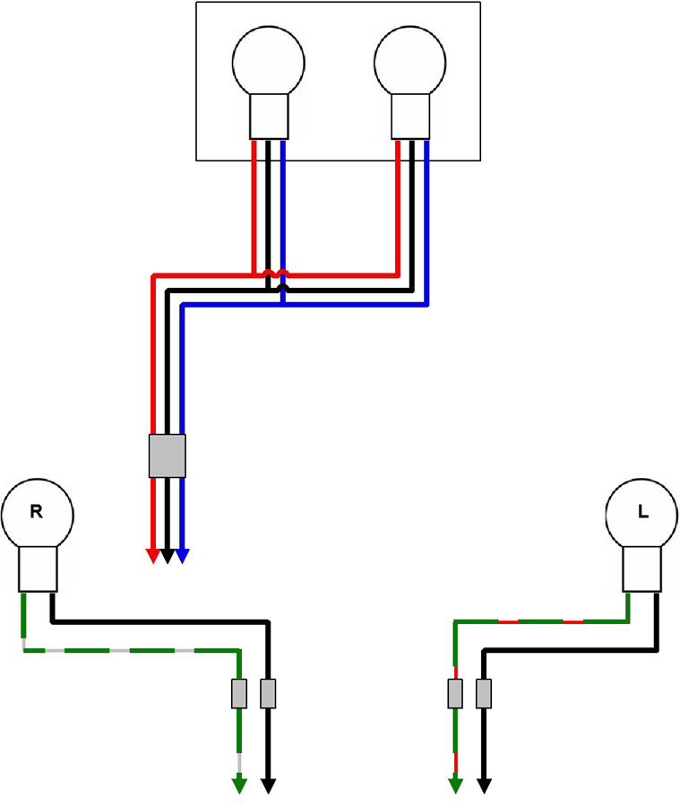 On the right is a wiring diagram of the brake and turn signal wiring
prior to the integrator installation. Click on the diagram for a larger
version.
On the right is a wiring diagram of the brake and turn signal wiring
prior to the integrator installation. Click on the diagram for a larger
version.
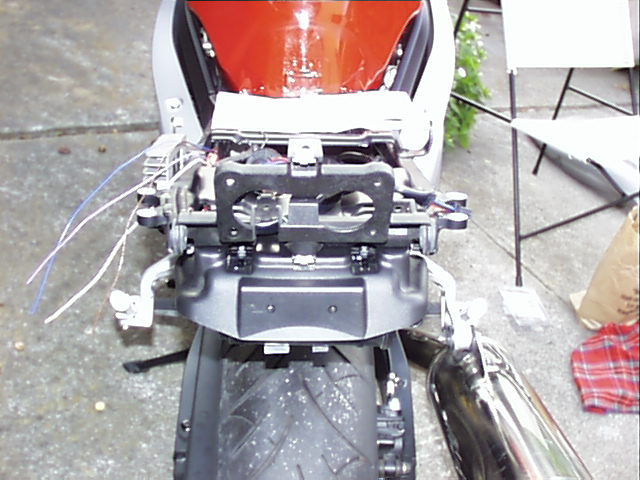 Reattach the tail
light assembly but remove the lens from the mounting
bracket. Remove the bulbs from the mountings and remove the wiring harness that
leads to the tail lights.
Reattach the tail
light assembly but remove the lens from the mounting
bracket. Remove the bulbs from the mountings and remove the wiring harness that
leads to the tail lights.
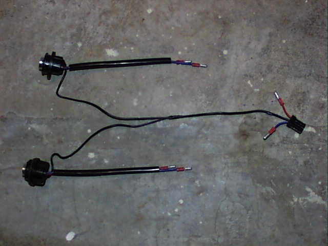
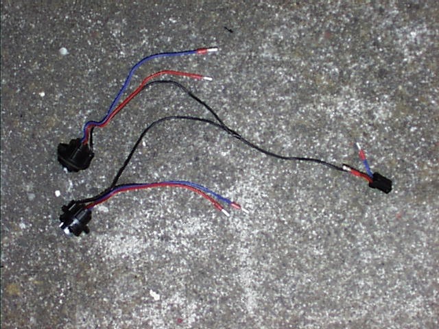
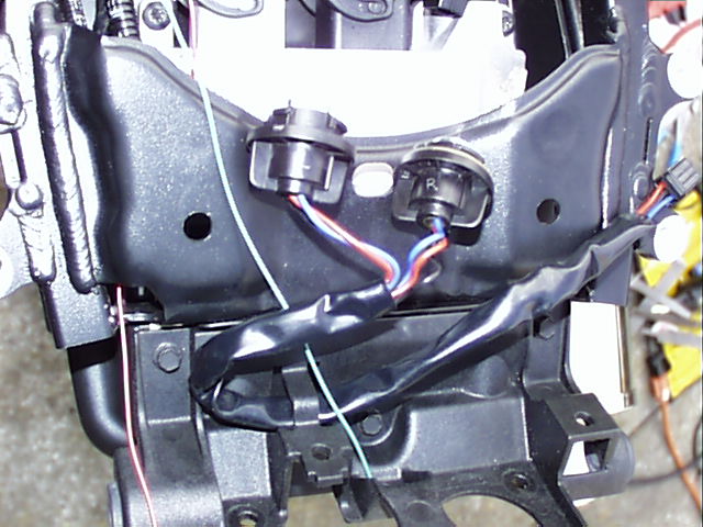 See the three pictures below to help guide you through
the next set of instructions. Cut the plastic sheathing away from the entire
length of the wiring harness. After you remove the sheathing, there will be a
piece of tape which covers the point at which the red and blue wires split (left
picture below).
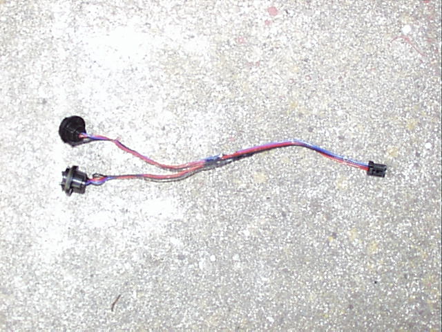
Remove the tape from the red and blue wires and cut the red and blue wires,
leaving the black wire intact. Crimp male bullet connectors on the ends of the
red and blue wires (middle picture below). Finally, I shrink-wrapped the red and
blue wires for a more professional look (right picture below).
See the three pictures below to help guide you through
the next set of instructions. Cut the plastic sheathing away from the entire
length of the wiring harness. After you remove the sheathing, there will be a
piece of tape which covers the point at which the red and blue wires split (left
picture below).
Remove the tape from the red and blue wires and cut the red and blue wires,
leaving the black wire intact. Crimp male bullet connectors on the ends of the
red and blue wires (middle picture below). Finally, I shrink-wrapped the red and
blue wires for a more professional look (right picture below).
Install the modified OEM harness back into the tail light assembly and run the OEM connector back to where it plugs in. We are only putting the harness back into the back at this point so we can measure the amount of wire needed when we install the integrator in the next step so there is no need to snug everything up.